Positional Tolerance - Bonus / Datum Shift / ASME Y14.5M - Clarification

C

CandidQuality

:deadhorse:

I'm sure I've simply missed the exact answer I am hunting for. I'll make the question clear, and please feel free to point it out. Currently have a copy of
ASME Y14.5M-1994 but doubt any better clarification in the 2009 standard.


Positional tolerance
Assumed correct:
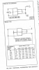
datum c bore has a positional tolerance of .007mmc to datum A, and it's diameter tolerance is +.006/-0. This gives the feature a maximum positional tolerance of .013 with the largest passing bore.
Assumed correct:
datum b bore has a positional tolerance of .060mmc to datum A, and it's diameter tolerance is +.006/-0. This gives the feature a maximum positional tolerance of .066 with the largest passing bore.

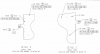
Now a reference frame for the hole(size +.006-.000) in question is .030MMC to A, B@mmc, C@mmc.

Assuming the hole is at the minimum diameter. The hole gets a positional tolerance of .030 from the first box of the feature frame. It should also be getting 1/2 the bonus from the -B- and -C- datums.

Down to the actual question:
Does that mean it gets 1/2 of the .066 from -B-? or only half of the .006 for the actual diameter. I have not seen a single example with a table showing anything where the datum has it's bonus. Every single example the datum has a 0 tolerance.

Without complicating it to discuss multiple holes, how would the single hole be treated. And where, exactly, is that stated from the specification. For example a table that show the datum shift bonus is in figure 5-48 on page 144. This is specific to positional tolerancing for coaxiality, but shows the concept i'm after.

As always I appreciate the help. Hope everyone is having a good holiday season.
 

Stijloor

Leader
Super Moderator
Re: Bonus/datum shift/ ASME Y14.5M

Can you attach a drawing or a sketch? It would help us and eliminate all guesswork.
 

Michael_M

Trusted Information Resource
Re: Bonus/datum shift/ ASME Y14.5M

I do not have the standard handy, I am answering based on my experience.

Using the following feature frame as an example:

(tp dia.006m A Bm Cm)

The actual diameter of the hole the feature is calling to has a true position of .006 + (highest allowable dimension-actual dimension).

The secondary and tertiary features have max as well (I typically ignore these bonuses as they really complicate things and if you need these bonuses you really did something wrong). However, you add (Highest allowable tolerance-actual dimension) for each one.

So Datum -A- is the top flat surface (gaining 0 bonus). Datum -B- will be something that aligns the part, lets say a side. the side has an actual tolerance of .002. So at max you can add .004 (+/-.002 gives a total of .004), and datum -C- is a hole diameter with a tolerance of .001 giving you .002 at max.

However, rarely are you running at max material so we will say you are running at perfect nominal. The hole you are measuring is +.006/-.000 so we will say it is at +.003, this gives you .006 +.003 + .002 (from Datum -B-) +.001 (from Datum -C-) or .012 true position. But remember when you measure the part, you must account measure from 'perfect' location, not from actual because you are using bonuses from -B- and -C- (even though we say we are at perfect for the above example).

The 'perfect' location is the reason I ignore the bonuses from -B- and -C- in general. I hold to the .009 true position and measure from actual locations.

Confused yet (don't worry, your not the only one)? If I get time, I will attempt to draw up a dirty print that shows what I am talking about.
 

Stijloor

Leader
Super Moderator
Re: Bonus/datum shift/ ASME Y14.5M

That would be very helpful! In case you look at examples in the applicable GD&T standard, it would be nice to give us the page and clause/figure reference.
 
C

CandidQuality

Re: Bonus/datum shift/ ASME Y14.5M

Ill drop it in monday. Unfortunately I left work before checking my messages.
 
C

CandidQuality

Re: Bonus/datum shift/ ASME Y14.5M

Pertinent section attached. And do remember, the positional tolerance of -B- is .060MMC per a note. I've also attached a clip of the figure 5-48 which only addresses a non-bonused datum feature.

Thanks again for the help.
 

Attachments

  • positional tolerance question.PNG
    positional tolerance question.PNG
    27.3 KB · Views: 864
  • figure 5-48.PNG
    figure 5-48.PNG
    20.5 KB · Views: 479

Michael_M

Trusted Information Resource
Re: Bonus/datum shift/ ASME Y14.5M

Regardless of where -B- and/or -C- are located (within the tolerance), you only gain a bonus based on the actual size(s) of the holes (again, so long as they are within tolerance).

If -C- is using all .013 (.007 base + .006 from -B-), the bonus of datum -C- for the other holes is only the diameter of the hole.


As a general note that I use a reference when explaining to people the use of geometric tolerances. If you have a general tolerance of +/-.005 in both X and Y, that calculates to true position of .0141. I use this to show people that a true position of .014 is not really that much.
 
C

CandidQuality

Thanks for the clarification based on what you've seen. I've seen nothing to contradict what you are saying Michael. But I've also never seen bonus tolerance on a datum really addressed in the specification. I'm having a hard time understanding why my datum -B- can shift .067, but my -C- can still only shift a max of .0165(.006 size+.007 position +.0035((half of -b- size only completely ignoring the other .060)). If you or anyone else can show a section in the spec that addresses this I would appreciate the hard data.

And not to make it more difficult, but does the same apply to the tolerance allowed on the edge trim then? The physical difference in those possible extremes of the pin up locations -B-, and -C- would add up to an edge trim position of +/-.045 on an edge with a .030 position(or +/-.015) as shown. As this part is 8 feet in between -B-, and -C-. It does make a massive difference.

The largest issue is that we still have no proper way to lock in a compound contoured surface when defined as the primary datum. You'd think 10 years after they write a spec someone would have resolved that by now.

Appreciate the responses. Definitely need to look into a course on the more advanced sections of GD&T.


BTW,
Agreed we are doing something terribly wrong. But since I can only report current state, nothing I can do to correct how badly the parts are being created. Were I in control, nothing would be produced further away from nominal than a third of the tolerance. I compensate by ensuring I'm not directly below the flight path of any plane we have a part on, and I don't fly.
 

Kingsld1

Involved In Discussions
I think that you have been misinformed about how datum shift works. There is no simple addition of additional tolerance from datums.

I'm assuming that the feature, B, and C are holes and A is a plane. A hard gage for it would consist of another plane to at as a datum simulator for A and pins at the minimumally allowable size for B and C. Depending on the size (and form) of the datum holes the part could shift in any number of ways. Use of the gage would consist of placing the part in the gage and shifting it on the datum A simulator until the pin for the feature falls in or you are satisfied that there is no possible way for it to go in. There are an infinite number of positions that the part could move within the gage.

If it's not possible to build a hard gage, paper gaging is an alternative. Don't think that I can explain it properly as I've barely used it myself. Try a Google search.

Don Day at TechEase has very good free explanations of GD&T topics at their website. I'm pretty sure that datum shift is one of the topics.
 
C

CandidQuality

Actually if you look at my attached 5-48 diagram, you will see exactly that in at least one case the math is simple. I do not have any evidence showing that diagram applies to my question though as this is a table applied to concentricity, and only addressed change based on the allowed diameter. I have yet to see anything address any possible bonus from a datum having a mmc that applies after that single feature. I'm obviously misinformed. Just trying to pull it out from the specification in an exact paragraph, and havn't found it yet.
Unfortunatly Datum -A- is a compound contoured surface. Extremely complicated (outer skin of aircraft). Check fixtures would range into the 20k per part and have already been deemed unnecessary by the President at any cost(silly imaginary profit margins).

I have seen generic references to "applies 1/2 of the tolerance" but without a single example covering a datum with a MMC shift allowed, I'm unsure. And from what I've had a chance to read since this qquestion first came to play, I agree that the answer is not linear. CMM software cannot be used due to the compound curved datum -A-, but I would still want the ability to verify it was using the proper tolerances.

Again thanks for the information. I'm trying to contact ASME directly, but have no idea if I will get a response ever, much less over the holiday. In the interim, I will keep reading the links in the hopes that someone has defined this well enough for me to grasp.
 
Top Bottom