IEC 60601-2-27: What does "linear within ±20% of the full scale output" mean?

S

smallbear

I'm conducting tests per IEC 60601-2-27. I have a particular question regarding Clause 201.12.1.101.1, Accuracy of Signal Reproduction. The requirement is: "Input signals in the range of ±5 mV, varying at a rate up to 125 mV/s, shall be reproduced on the output with an error of ≤ ±20 % of the nominal value of the output or ±100 μV, whichever is greater."

The test is simple:
1. Set gain to 10mm/mV.
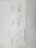
2. Input a triangular wave.
3. Adjust input signal amplitude to 100% full scale peak-to-valley output.
4. Decrease input signal amplitude by factors of 2, 5, and 10.

Success criteria:
For each signal amplitude in (4), the displayed output shall be linear within ±20 % or ± 100 μV of the full scale output.

My question is:
How do you interpret the success criteria? I'm assuming the +/-20% is allowing a margin of error for output signals that are not perfectly triangular, which means it's acceptable to have a noisy/distorted signals?

I'm currently interpreting this as a 20% linearity on a single test case. It's not making sense to me on how this 20% applies to the full scale output.

Any help would be greatly appreciated.

Thanks.
 

Eamon

Involved In Discussions
I interpret this as follows. I welcome corrections from those more knowledgeable.

A triangle wave is a sequence of linear (straight-line) slopes. The output has to be linear and accurate as specified. As such, at no point must it depart from the nominal trace by a vertical amount of more than 20% of the full-scale output, or 100μV, whichever is greater.

This will cover nonlinearity as well as scaling (gain) errors. I agree it is a rather large allowance for nonlinearity, but this might be because for the most part they are testing the gain accuracy. (If lots of nonlinearity appears while doing the test, the designer will probably want to fix it even if it technically doesn't fail.)

I don't have the standard in front of me, but while excessive noise could conceivably cause a deviation that would make this test fail, isn't there a separate requirement for noise that would probably end up being stricter than this one as far as noise is concerned?

Eamon
 
S

smallbear

Eamon,

Thanks for your input. It sounds like the margin of error for linearity is computed once at full scale output (i.e. 20% of full scale output), and then applied to subsequent test cases where the input signal is decreased. I've outlined this in the attached photo. Would you agree?

In our case, our full scale output isn't linear to begin with (i.e. slightly curved due to RC filtering), but I could imagine this criteria can still apply.
 

Attachments

  • 20161004_135045.jpg
    20161004_135045.jpg
    123.4 KB · Views: 209

Eamon

Involved In Discussions
Hi smallbear,

I can't claim to be an expert, and I don't have the test in front of me, but to me, it is kind of common sense that unless another meaning is made explicit, "full scale" is to be taken in the context of each measurement being made.

That's what it means, for example, when you are talking about an oscilloscope screen. It's pretty clear that percent of full scale at 5mV / division is not referenced to what it would be at the scope's least sensitive setting, say 50V / division.

Linearity is typically more of a problem the bigger the input signal. According to what you've reproduced of the test sequence, the greatest amplitude is covered first. Unless there is some weird stuff going on (like for example distortion where the signal crosses through zero) there shouldn't be any problem meeting the accuracy and linearity requirements at lower levels, even if the error threshold needs to be considered to scale down with the signal.

To put it a bit differently, equipment that fails linearity at low levels but passes at higher levels may have some issues that need looking into.

Eamon
 
S

smallbear

Eamon,

Thank you for clarifying. I agree with your interpretation.

Regards,
 

Peter Selvey

Leader
Super Moderator
This is one of the tests which has been around for years since articulated arm type ECGs which could potentially have a lot of distortion due to the mechanical aspects of the system.

Although IEC 60601-2-27 first included performance tests in the 2005 edition, many of the test are derived from much older ECG standard such as OIML R90 (1990) and very old national standards in US, China etc.

The original test in the 2005 edition started at 10% and then increased up to 100%, which makes sense if you think about it from a mechanical system point of view, i.e. start at 10% full scale, ramp it up to 100% and see what the error is and make sure it is within ±20% - a relaxed limit appropriate for mechanical systems from 1897.

But does not make sense for modern ECGs with 40mm dot matrix thermal printer strip since starting at 10% is only 4mm and trying to adjust that is quite difficult.

So in the 2011 edition they changed to starting at 100% and working down to 10%. That actually makes the test much easier to pass, and combined with the far higher accuracy in modern digital ECGs, will leave more than one test engineer scratching their head as to what the ?? is this test all about.

As a side note, I have noticed some modern ECGs seem to exhibit something like op-amp slew rate limitation (which may come from high gain low noise op-amps, struggling to drive capacitors in the high pass filters) and occasionally compression around the rail voltage. So, non-linearity can still be a problem. But the tests in the standard don't seem to really designed around the issues for modern electronics.
 
Last edited:
Top Bottom