C
Coleman Donnelly
I have a callout on my print that i have never seen before - hopefully someone here can help me interpit what the print means:


I have a callout on my print that i have never seen before - hopefully someone here can help me interpret what the print means:

Sorry this picture didn't turn out very good...
Engineering standard that print is drawn to is FAD ?
Yes essentially it looks like this
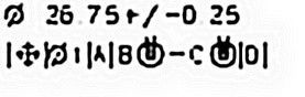
|(True Positon symbol)|(Diameter symbol)1|A|B(mmc symbol) - C(mmc symbol)|D|
There is now way to import GD&T symbols that i know of for the font style on this forum...
The confusion that i have is the |Bmmc - Cmmc| portion - i have never seen this before... Typically i only have A|B|C this one shows A|B-C|D...
Hope this helps explain my problems!