What is the "System" to be considered for System FMEA

loic trocme

Registered
Hello.
About System FMEA :
  • Should I consider the product I design as "the system", and analyze "only" the possible failures of the functions realized by my product,
  • or should I consider "the system" my products with all the sensors and actuators I'm connected with, and analyze the possible failures of these external sub system?
If it is second choice, do I have ton consider also the internal possible failures of my product, or will this be covered by Design FMEA?
Thank you
 

Miner

Forum Moderator
Leader
Admin
So, there are two different questions being asked here.
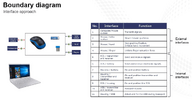
  1. Q1 - At the system level, you evaluate your product and the interfaces between your product and the external super-system. A boundary diagram (see example below) will help you visualize this. Do not evaluate potential failure modes in the sensors and actuators themselves but do evaluate potential failure modes in the interfaces to those sensors and actuators that could be caused by your product.
  2. Q2 - The system FMEA focuses on functions and interfaces unique to the system as a whole. See What is unique about a System FMEA? for more detail. Anything that is not unique to the system will likely be handled by the lower-level Design FMEAs.

1695300332971.png
 

loic trocme

Registered
Thank you for the fast and comprehensive answer.
The internal interfaces, as shown in the example you provide, are focus on physical interfaces.
If the product is "just" a PCB with some electronic, would you suggest to consider as Internal interface the connection between PCB and connector, for example, or to list the functions embedded in the produc and the interfaces between these functions?
 

Miner

Forum Moderator
Leader
Admin
It would depend on whether those functions and interfaces are unique to the system as a whole. If those internal interfaces would be covered by a design FMEA then address them at that level.

Don't be confused by the boundary diagram. It is not necessarily unique to the system FMEA. The same boundary diagram might be used at the system level or a deeper design FMEA level. If you went all the way down to a component level FMEA, you might need a more detailed boundary diagram.
 

Miner

Forum Moderator
Leader
Admin
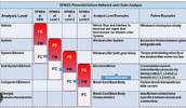
I presume that:
  • FE = Failure Effect
  • FM = Failure Mode
  • FC = Failure Cause
 
Top Bottom