Calculating (Approximate) Parallelism

K

kdisarno

I found the other parallelism topics in this forum, so here goes nothing...

I'm trying to take my best guess/approximate of parallelism for a manufactured part. I'll just simplify it and call it a block, because that's practically what it is.

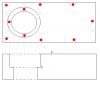
Did I mention this was old-school yet? Well, now I did. I don't have any fancy equipment, granite tables, or digit gauges, even. All I have are 10 points and the deviation from nominal. The points are taken at the locations in the attached print :D; 7 points on top, 3 on the counterbored surface below. From each point, I get, like I said, deviations from nominal +0.022 or -0.013.

How do I calculate the (approximate) parallelism of D to F, the counterbored surface to the top surface?

I'm more looking for a process (or, for the lack of a better word, an algorithm)...take the highest point on F, subtract the flatness of D...whatever it may be.

Thanks,
Keith
 

Attachments

  • Calculating (Approximate) Parallelism
    block.PNG
    1.4 KB · Views: 256

Jim Wynne

Leader
Admin
Welcome to the Cove. :bigwave:

Where did the points come from? In establishing parallelism (determining parallelism error), you must have a datum plane and a plane that's compared to the datum plane. For example, in your drawing the top surface would probably be datum "A" and the counterbore surface would be specified to be parallel to "A" within some value x. If you had a CMM, you would establish a plane on the top surface (taking points as in your sketch) and then probe the counterbore surface, and the CMM software would calculate the parallelism error.

If you were working on a surface plate, you would have to find a way to locate on the top surface (it being parallel to the surface plate) and then run an indicator across the counterbore surface or in pinch, vice-versa. Parallelism error would then be established on an "FIM" (full indicator movement) basis.

Since you say you have none of these things, without knowing where your points came from it's impossible to give you any guidance.
 
K

kdisarno

The delta's are coming from a gauge we have set up with dial indicators on them.

I'm thinking I need to arbitarily set a plane...like at the average deviation of the top surface or at the highest peak of the top surface, parallel to nominal.

Obviously the top surface should be completely flat (well, the flatness spec is 0.050mm), but if I come up with a best fit plane (measurements would be the residuls...I'm a statistican by trade) that will have to become my new normal/reference plane. From there can I look at the measurements from D?

- Keith
 

bobdoering

Stop X-bar/R Madness!!
Trusted Information Resource
I am trying to think of a way that you can actually do this easily. For your tolerance, measuring without a granite table and a gage that reads in microns is pretty much a waste.

But, to measure parallelism using the bottom of the counterbore as your datum, you would have to shim the underside of the part until the indicator reads the same value on the 3 points on the surface of the counterbore. That sets your plane. Then you would put the indicator on the upper surface and scan across the surface, or pick important points as you have, and look for the difference between the highest and lowest point.

Flatness is actually tougher to measure correctly.

Typically, you would set up the surface to measure on 3 identical gage blocks as “legs”. Then you scan the surface with an indicator (that would be on the underside - the surface on the gage blocks - not the top surface!), reading the difference between highest and lowest.

Since your tolerances appear to be in the micron range, you need equipment that is suitable for that tolerance. Otherwise, it’s like a dentist using a yardstick (meter stick outside the U.S.)
 
G

Geoff Withnell

I am trying to think of a way that you can actually do this easily. For your tolerance, measuring without a granite table and a gage that reads in microns is pretty much a waste.

But, to measure parallelism using the bottom of the counterbore as your datum, you would have to shim the underside of the part until the indicator reads the same value on the 3 points on the surface of the counterbore. That sets your plane. Then you would put the indicator on the upper surface and scan across the surface, or pick important points as you have, and look for the difference between the highest and lowest point.

Flatness is actually tougher to measure correctly.

Typically, you would set up the surface to measure on 3 identical gage blocks as “legs”. Then you scan the surface with an indicator (that would be on the underside - the surface on the gage blocks - not the top surface!), reading the difference between highest and lowest.

Since your tolerances appear to be in the micron range, you need equipment that is suitable for that tolerance. Otherwise, it’s like a dentist using a yardstick (meter stick outside the U.S.)

Actually, it is much easier to measure flatness by placing three screw adjustable jackstand under the part, on the opposite side from the side being checked for flatness. Use the jackstand adjustment to bring the point on the surface being checked over each jackstand to zero. This establishes the plane. You may then sweep the surface and get FIM for flatness. This lets you indicate (and read!) on the top of the part.

Geoff Withnell
 

bobdoering

Stop X-bar/R Madness!!
Trusted Information Resource
Actually, it is much easier to measure flatness by placing three screw adjustable jackstand under the part, on the opposite side from the side being checked for flatness. Use the jackstand adjustment to bring the point on the surface being checked over each jackstand to zero. This establishes the plane. You may then sweep the surface and get FIM for flatness. This lets you indicate (and read!) on the top of the part.

It can be a toss-up - read from the top of the part, but get jackstands and mess with them until they zero out, or use simple gage blocks, but work under the part. As usual, the personal preference will depend on what resources you have, what patience you have. At the micron level, it may also depend on how much coffee you drank. But, it is always nice to have options.
 
K

kdisarno

I guess I'm gonna have to do this mathematically then.

I'm gonna have to get the x,y,z points and fit a plane through the three points on D, the counterbored surface. I'll come up with 4x + 8y -3z = 2 or something. Then I will have to adjust the points on F with reference to this weird plane in space.

We don't claim or really desire to be accurate to the micron (0.001mm). We're currently doing a gauge R&R to try and qualify the gauge.

Not that I have a CMM, but shimming this or that seems so...ogre-ish. I'm shocked that you have to jump through hoops on a CMM. If the machine knows an 'infinite' amount about the part, it should surely be able to give you anything you wanted.
 

bobdoering

Stop X-bar/R Madness!!
Trusted Information Resource
We don't claim or really desire to be accurate to the micron (0.001mm). We're currently doing a gauge R&R to try and qualify the gauge.
To measure with an acceptable resolution, you should have a minimum 10:1 ratio to your tolerance. Your tolerance is 50 microns, so your measurement system should have a 5 micron resolution (not including error). So, that's why I say micron range.

Not that I have a CMM, but shimming this or that seems so...ogre-ish.

Well, it's neither easy nor pretty...but it is, as you say, old school.

I'm shocked that you have to jump through hoops on a CMM. If the machine knows an 'infinite' amount about the part, it should surely be able to give you anything you wanted.

Oh, it is a lot easier with a CMM. Generate a plane that goes through your 3 counterbore points, then measure the opposite surface on several points, and it spits it out. That's why people love them! No shims required - it does it all in coordinate math.
 
T

True Position

The formulas you want to calculate exist, but they exist in CMM software since they are pretty complicated.
 

Jim Wynne

Leader
Admin
I guess I'm gonna have to do this mathematically then.

I'm gonna have to get the x,y,z points and fit a plane through the three points on D, the counterbored surface. I'll come up with 4x + 8y -3z = 2 or something. Then I will have to adjust the points on F with reference to this weird plane in space.

We don't claim or really desire to be accurate to the micron (0.001mm). We're currently doing a gauge R&R to try and qualify the gauge.

Not that I have a CMM, but shimming this or that seems so...ogre-ish. I'm shocked that you have to jump through hoops on a CMM. If the machine knows an 'infinite' amount about the part, it should surely be able to give you anything you wanted.

The CMM software, like any other software, "knows" only what it's told. GIGO--garbage in, garbage out.

Charles Babbage, inventor of the first mechanical "computer," is famous for having observed, "On two occasions I have been asked,—'Pray, Mr. Babbage, if you put into the machine wrong figures, will the right answers come out?' ... I am not able rightly to apprehend the kind of confusion of ideas that could provoke such a question."

The proper way to approach this problem depends on what, exactly, you need to know, and why you need to know it. If you're trying to understand the part as a component in your own design and need to know something about how things will fit together, and tolerance stacks, it's a different kind of problem than if you're dealing with someone else's drawing and need to make sure you're meeting the specifications.

If the latter case is true, you need to think about not only how you're going to measure the thing, but how the customer is going to measure it, if at all. If you're using relatively crude tools and seat-of-the-pants calculations and the customer is using a CMM, you'll need to be prepared for some difficult questions.

The question, "How am I going to measure this?" needs to be asked at the quotation stage, or at the point where specifcations are being developed.
 
Top Bottom